What is a Thermostat Wiring Diagram?
Decoding the Purpose of a Thermostat Wiring Diagram
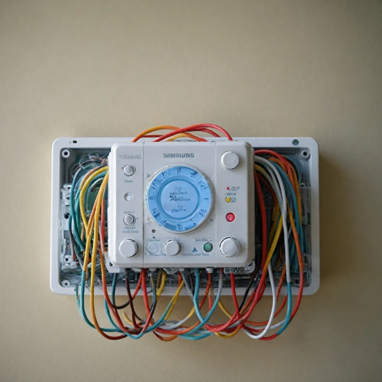
Thermostat wiring diagrams are essential tools for understanding the intricate connections within an HVAC system. These visual guides provide a clear representation of how various wires and components, such as the thermostat, transformer, and air handler, are connected to control heating and cooling functions. A thermostat wiring diagram acts as a roadmap, aiding in the installation or troubleshooting of a system, whether it involves a standard furnace or a sophisticated heat pump. It visually presents how thermostat wires correspond to specific terminals on a system and helps ensure correct installation and operation, particularly when dealing with multi-stage heating or cooling setups. Understanding these diagrams is crucial for successfully setting up smart thermostats, as these advanced systems involve more complex wiring compared to traditional ones. Challenges can arise, especially around components such as the reversing valve in systems using heat pumps, where the correct wiring ensures the system can effectively switch from heating to cooling modes. To delve deeper into the details of wiring a smart thermostat, including recognizing the functions of different wires and terminals, check out this comprehensive guide. Here you will find a wealth of information that complements our exploration into thermostat wiring diagrams, helping to manage both common and complex systems effortlessly.Key Components of a Wiring Diagram
Essential Components to Grasp in Wiring Diagrams
Understanding thermostat wiring diagrams is vital to ensure your HVAC system functions optimally. These diagrams serve as blueprints encompassing various elements and pathways that facilitate the heating, ventilation, and air conditioning processes. Here, we delve into the crucial components you must familiarize yourself with:- Thermostat Wire Types: Different wires like C (common wire), R (power wire from the transformer), Y (cooling stage), W (heating stage), and G (fan) form the backbone of thermostat operations. Color codes often help identify these wires, yet it’s crucial to verify with your system’s particular diagram.
- Wire Terminals: A terminal is where a wire connects to the thermostat or another component. In smart thermostats, terminals such as O/B are pivotal, as they control the reversing valve for heat pumps.
- Transformer Connection: This is crucial in providing power to the system. It transforms the incoming power into a usable voltage for the thermostat and other components.
- Heat Pump Configuration: Heat pumps frequently feature more intricate setups involving additional stages for both heating and cooling. Proper comprehension of the pump thermostat intricacies, including features like auxiliary and emergency heat, is essential.
- Air Handler and Furnace: Knowing where these units fit within the overall diagram allows for greater control over both the heating cooling process and air distribution.
Common Wiring Configurations
Exploring Diverse Wiring Configurations for Thermostats
When it comes to thermostat wiring, understanding the configurations plays a crucial role in ensuring effective communication with your HVAC system. With the myriad of systems and smart thermostats available, knowing the nuances of various wiring setups becomes essential.
Common thermostat configurations are typically influenced by the type of HVAC system in use. For instance:
- Single-stage wires: Typically found in simple HVAC systems, where one wire controls the heating and another controls the cooling.
- Two-stage systems: These incorporate additional wires for more sophisticated control over heating and cooling, such as managing varying outputs of heat or air conditioning. You might notice additional wires connected to terminal thermostat components.
- Heat pump wiring: This configuration requires distinct connections, commonly including an O or B wire responsible for the reversing valve, which alters the mode between heating and cooling without requiring separate systems.
- Multi-stage HVAC systems: Designed for more advanced systems, using even more wires for precise control over various stages of heating and cooling, often integrating complex setups with furnaces and air handlers.
In all these configurations, the common wire (C-wire) plays a fundamental role, providing continuous power to the thermostat, crucial for a smart thermostat to function optimally. Additionally, various colors in thermostat wires help in identifying the respective functions they perform, aiding users during installation or troubleshooting.
Attention to these configurations ensures your system correctly responds to environmental conditions, achieving proper heating and cooling. For further insights on setting up different thermostats or understanding more intricate details of heat pump setups, you might consider checking out this comprehensive guide.
Challenges in Smart Thermostat Wiring
Facing the Complexities of Smart Thermostat Wiring
Smart thermostats have revolutionized how we control our HVAC systems, but wiring these devices can present unique challenges. When transitioning from a traditional thermostat to a smart one, the installation becomes more intricate due to the advanced functionalities and requirements for optimal operation. One of the main challenges is the need for a strong power supply. Smart thermostats often require a continuous source of power to maintain connectivity and functionality, and this typically comes from a wire known as the common wire or C-wire. Older HVAC systems may not have this wire readily available, leading to potential complications during installation. Another complexity arises with heat pump systems, especially those involving a reversing valve. Thermostat wiring needs to be precise to ensure the heat pump functions correctly. Incorrect wiring of the reversing valve can result in the system heating when it should be cooling or vice versa. Wiring configurations vary greatly depending on whether your system is single-stage or multi-stage. Multi-stage systems, which provide more efficient heating and cooling, require additional wires and careful attention to how these thermostat wires connect to their respective terminals. The wiring diagram becomes your best friend in this scenario, but misinterpretations can lead to significant issues such as system inefficiencies or failures. Moreover, color codes used in wiring may differ from one HVAC manufacturer to another, which can further complicate the wiring process. For individuals unfamiliar with HVAC systems, dealing with these wires and terminals can be daunting. However, having a comprehensive understanding of the wiring diagram associated with your thermostat can mitigate many of these challenges and smoothen the process of installing a smart thermostat.Safety Tips for Handling Wiring
Practical Guidance for Safe Wiring Practices
When handling thermostat wiring, safety should be a top priority. A thermostat wiring diagram will help you navigate the intricate web of wires and configurations associated with HVAC systems. However, it’s crucial to keep certain safety tips in mind to avoid potential hazards.- Power Off: Always ensure that the power to your HVAC system, including the transformer and air handler, is completely turned off before attempting any wiring tasks. This precaution prevents electrical shocks and protects both you and the system components.
- Identify Wires: Before you start, clearly identify each thermostat wire by its color codes and purpose. This will help confirm each connection’s compatibility with your HVAC system’s terminal arrangement, thereby avoiding incorrect wiring that might damage your equipment.
- Secure Connections: Ensure that all wire connections are secure. Loose connections can cause malfunctioning or even shorts in your heating and cooling system. It’s essential that every wire fits snugly into its respective terminal thermostat to maintain stable system operations.
- Handle with Care: Be gentle when dealing with thin thermostat wires. Rough handling or bending can cause the wires to break, affecting your entire system’s functionality including heat pump thermostat settings.
- Reversing Valve Guidance: If you have a heat pump system, special attention should be given to the reversing valve wire. This component is essential in switching between heating and cooling modes, and any incorrect wiring could impact the efficiency of heat pumps dramatically.
- Consult Professionally: When in doubt, or if the wiring diagram seems too complex, consider consulting a professional. An expert can not only assist in interpreting the wiring diagram but also ensure that your thermostat installation complies with safety standards.
Troubleshooting Wiring Issues
Troubleshooting Wiring Problems in Smart Thermostats
When dealing with smart thermostat wiring, problems may arise even after following a detailed wiring diagram. These challenges require a careful approach to ensure your HVAC system operates smoothly. Here are some methods to troubleshoot typical wiring issues:- Verify Wire Connections: Ensure every wire is connected to the correct terminal. Mistakes often occur with terminals such as the R (power), Y (cooling), and W (heating). Double-check the wiring diagram for guidance.
- Inspect for Loose Wires: Loose connections are frequent culprits behind inefficient system performance. Secure any loose wires in place on the thermostat terminal to maintain consistent power flow.
- Test System Compatibility: Some thermostats may not be compatible with specific HVAC systems, particularly those involving unique setups like multiple heat stages or heat pumps with reversing valves. Refer back to the components and configurations sections for insights.
- Color Code Checks: Ensure that wire colors align with the standard color codes outlined in the wiring diagram. An incorrect color hookup can lead to improper system operation.
- Assess Transformer Issues: If power problems persist, investigate the transformer. An underperforming transformer can undermine the thermostat's ability to power the HVAC system effectively.
- Review HVAC System: Confirm that the HVAC system, including the furnace and air handler, is functioning properly. Issues in these larger systems can sometimes reflect as thermostat problems.
- Test Multimeter Readings: Use a multimeter to verify proper electrical flow through the wires. It helps to pinpoint if a lack of current is the source of your issues.
